I've managed to get some of my A4 LCD panels (actually Epson ECM-A0557 panels) to work on the external video output from an ARM7500(FE), which appears as the genlock connector on the A7000(+) board.
An accurate pinout is here. This datasheet appears to be incorrect. Other than the pinout, the diagrams in that datasheet bear a very striking resemblance to those in the Hitachi LMG5278XUFC datasheet which may be useful. ARM's LCDs on 7500 application note is useful for programming.
With the connectors on the left hand side of the LCD facing the front, if they are numbered 1-20 from top to bottom the required cable is:
Genlock connector                LCD
-----------------                ---
ECLK    6                        CP       5 and 15
ED0     8                        UD3      4
ED1     9                        UD2      3
ED2    10                        UD1      2
ED3    11                        UD0      1
ED4    12                        LD3     14
ED5    13                        LD2     13
ED6    14                        LD1     12
ED7    15                        LD0     11
HSYNC   1                        LOAD     7 and 17
VSYNC   2                        FRM      6
GND     4, 7 and 16              GND      9 and 19
                                 VCC      Join 8 and 18
                                 VEE      Join 10 and 20
VCC on both the LCD goes to a +5V supply. VEE needs to be driven from a variable negative voltage (variable for contrast) between about -13V to -18V. The quickest way to do this is shown below:
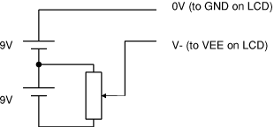
This needs to be able to deliver a few mA to the LCD. I used a 470R pot as I had one to hand, but this eats batteries very rapidly. Larger values could probably be used without ill effect. A better way is to use a voltage regulator for the negative voltage, or run it off a mains transformer. Dedicated LCD bias generating chips also exist. Bear in mind that any external supply must not have its negative rail connected to earth, otherwise it may short through the earth line.
The RISC OS driver module sets the VIDC for LCD mode on every mode change, and keeps it in 640x480x4bpp irrespective of what mode RISC OS thinks it is in - this is only sensible in mode 27. It also maintains the VIDC screen address registers every Vsync. Currently the pointer doesn't work as I haven't spent time fixing it. You can download it (in alpha state).
Page by Theo Markettos (email at theo [at@] markettos.org.uk), last modified 2008-01-23
Return to Theo's A4 pages.