This page details the upgrade of an Acorn 486SXL33 PC co-processor card for the Acorn Risc PC to use a 586 processor. They concern for the most part the first release of this card that used a Gemini I ASIC (I believe these cards had a code of ACA42, while Gemini II cards had a code of ACA52). They might work in principle with other PC cards, but this hasn't been tried.

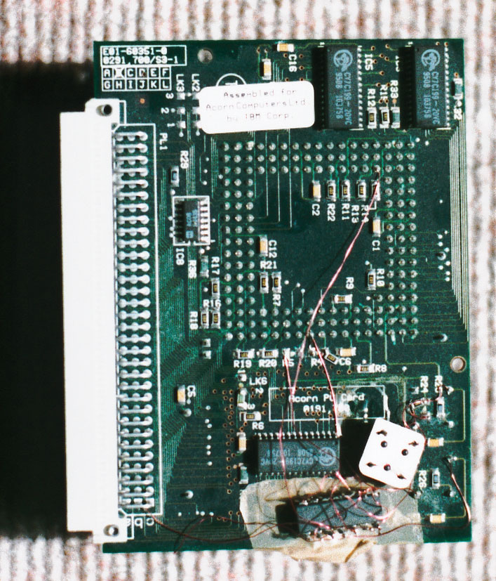
My upgraded card (click pictures for larger versions)
The following intructions were written by Freimut Matheus (FMatheus@t-online.de), and are reproduced here with his kind permission. I've successfully performed this upgrade, and I'll add some comments on my experiences when I get a chance (a quick email I sent has some more details). You might find (as I did) that these instructions are slightly contradictory to the ones on the Acorn Cybervillage - that is for an off-the-shelf upgrade module, while these are for a raw CPU. This set was the one that worked for me (with a raw CPU) - but it's advisable to read them in parallel anyway. Standard disclaimers apply - you attempt anything suggested here at your own risk, and neither myself or Freimut will be responsible for any damage caused as a result.
- Get hold of a new CPU - the fastest that will work is a 5x86-133 from AMD (note that's not a K5). These are CPUs with a 486 bus which come is 168/9 pin PGA package. If the CPU doesn't run off 5V (as the 5x86 doesn't), you'll also need a voltage adaptor to regulate the 5V the Risc PC supplies to 3.3V or the appropriate voltage for your CPU. Evergreen and others make all in one 'Overdrive' upgrades that include CPU and regulator on one board, although I haven't tried this.
- Desolder the old CPU
(the biggest problem I think. Be careful!!) - Open LK4 2-3 and close LK4 1-2, and open LK8 close LK5 1-2 with the 0 Ohm resistor from LK8 (all these LK's are on the topside of the PC card)
- Solder a 168pin PGA IC socket
- (now we are on the bottom side of the PC-Card)
Remove R4 and R5 open LK6 1-2 and close LK6 2-3 - Solder the IC 74ACT74 as shown below:
![[PC card latch schematic]](pccardug/pclatch.gif)
(the wires from the IC to R4 and R5 you must solder to the left "solder-area" from the old R4/R5, the rightside of R4/R5 was conected to a CPU pin). Note it must be an ACT74 or an AC74.
Please pay attention for the position of the 74ACT74. The best place for the IC is the solderside of the Card. Stick it upside down under the ASIC (into the little white bordered area) as shown below. Tip: Vcc is on pin 3 of LK6. The pinout of the CPU is shown below (note - solder the wires to the back of the socket on the card, not on any upgrade module you might have)
![[Pinout of 169 pin PGA socket]](pccardug/pcpinout.gif)
Freimut says: You can also get my original german article if it's usable to you. If you're in doubt or you have some questions - please email me!
Page by Theo Markettos and Freimut Matheus (email at theo [at@] markettos.org.uk), last modified 2001-07-28
Return to Theo's Acorn pages.