For some unknown reason, old fashioned valve wireless sets have always appealled to me. This is in part because of the simplicity of the circuits, and the nice large discrete components, and especially the lack of custom integrated elements! However it's certainly true that finding information on some of these old sets can be quite difficult, so I have tried to give some schematics and information which may prove useful to other people. The information naturally divides into that relating to:
I suspect some modifications may have been made, in particular some resistors have been introduced into the anode lines, and wrapped in insulating tape. The circuit seems very similar to that of the Cossor Melody maker (1928 version). The most interesting features are that the set is LW/MW and the regeneration control is arranged by rotating a piece of ferrite in the RF coil. The set was made using cossor parts (all the intervalve tranformers are stamped as Cossor).
My first repair project on an old wireless set was a Mullard MAS-90 4 valve set, which was made in about 1939, and which uses an intermediate frequency of 128kHz. The line up is Rectifier AZ1, Changer ECH3, IF amplifier EF9, output amplifier and detector EBL1. The set arrived in a very poor state. It had been sitting for a number of years in a damp basement and many of the components weren't even identifiable as radio parts, but it seemed like a good first project as there wasn't much that I could do to make the set worse. At some stage in it's life the AZ1 had failed and a repair had been bodged with the addition of an international octal holder and a GZ34. Fortunately the side contact holder for the AZ1 had been retained. As the filament voltage of the AZ1 is 4V and the GZ34 is 5V the rectification had obviously not been too efficient, and an "HT FAULT" tag from a radio shop was attached to the front of the set. I removed all the components from the chasis taking copious notes as I did, and cleaned everything thoroughly before beginning the long reassembly process (and of course finding the errors in my notes).
AGC is applied by changing the grid bias on the IF amplifier and Ouput valve. The EBL1 is a dual diode (one for AGC and the other for detection) and the pentode section acts as the power amplifier driving a permanet magnet speaker. The output stage is rather peculiar since it uses a feedback winding on the output transformer to apply a variable degree of negative feedback to the grid circuit (this seems a very early negative feedback example).
The glass Dial Scale is shown here after removal from the case (which is made of Bakelite), for cleaning. The scale is glass with the stations positions printed on it. I have a paper drawing which I could send you a copy of, should it be necessary for reconstruction of a scale of this type.
Above Chassis View of the MAS-90 before restoration. When I took this photograph some components has been removed for cleaning such as the tuning capacitor and all of the valves.
As a result of the damp in the basement all the wooden components had completely disintegrated so I have had to make copies of the base, speaker baffle and the back. The speaker baffle, being bent plywood was the most tricky. For speaker cloth I used a piece of open weave material which creates the correct effect, whilst not having exactly the correct patterning.
However I am missing the bakelite lever which projects through the left hand side and operates the bandswitch mechanism. I'm looking for a replacement, so please let me know if you find one spare!
I've got a lot of drawings of this set which should be appearing soon, including complete waveband switching details (it is a LW/MW/SW set!). If these are of any use to you then email me and I can probably arrange to send you a copy.
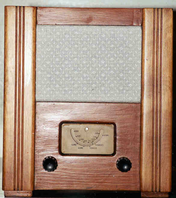
I have just finished the restoration of a Second World War Utility set
for the Cambridge Museum of Technology. This photograph shows the set in
its finished condition after all of the work had been done! An
account of the restoration provides some more details
about the set itself and the work involved in restoring one.
The utility set was made during the Second World war as a standard set. The Radio Manufacturers Association produced standard drawings which could be used by manufacturers, in order to construct a set using valves which were in current production (for the military), and which had a limited number of replacement parts needed to faciliate repairs This fitted into a long line of Utility products, such as furniture and clothing, designed and constructed to sturdy, useable, and make efficient use of manufacturing effort. Manufactureres had considerable leeway in using up old stocks of components, and pre-existing tooling, as a consequence of which there were numerous variants produced by the manufacturers. The manual supplied with the set (which I don't have a copy of) is very interesting since it suggests that the user make repairs to prevent wastage of technician's time recifying trivial faults.
Some features which puzzle me about these sets include the use of a point contact diode as detector and in this paricular one there is another one (possibly AGC). It turns out that these were part of a modification by someone who didn't understand the original AGC system, which used the supressor grid of the IF amp to Cathode path as an AGC voltage rectifier to produce the necessary delayed AGC. This was due to non-availability of the more usual pentode plus dual diode valves (such as the EBL1) from the wartime valve industry (not needed in CW demodulators?).
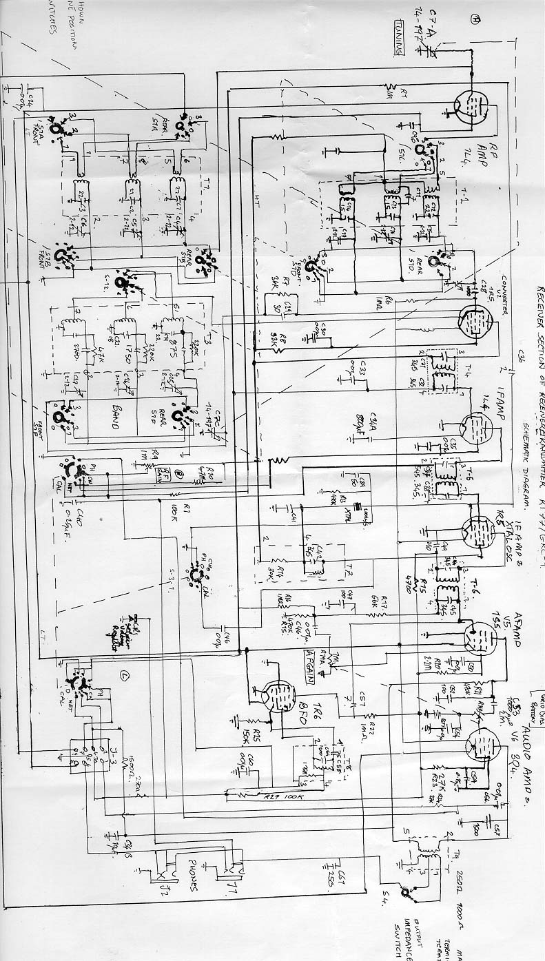
Until recently I used to say that `this is a set about which almost nothing is known'. However, thanks to VMARS, I have discoverd that it was a common NATO design, originating in the US and being made in various countries such as France and Belgium. This example is certainly French. It was made as part of a combined Tx/Rx set, the GRC-9 (photograph on the Army Radio Sales website). It seems that it was designed for use in the field from a hand cranked generator! It uses 1.5V heater valves. A circuit diagram reduced so that I couldn't read it was printed on the inside of the case. I've made an enlargement which is available as a JPEG. I have now obtained a copy of the maintenance manual, thanks to VMARS. Some of the valves (low current heater ones), are shown in this photograph, they were made for the French Services.
Set of valves 2 pounds 6 shillings.
[When ordering please state voltage and frequency of mains].
The construction drawings were originally blueprints and didn't scan that well;
A cleaned up schematic, and (less cleaned up)
layout diagram are available.