| Model | Description | Picture | Block Diagram | |
|---|---|---|---|---|
| EC958 | Basic Model | |
Block Diagram | |
| EC958 | Basic Model (slight fascia changes) | |
||
| EC958/1 | 40db Attenuator | |||
| EC958/7 | Digital LED kHz display, 40db Attenuator | |
Block Diagram | |
| EC958/9 | ISB version of EC958/7 |
| Alignment Frequency | Adjustments | |||||||
|---|---|---|---|---|---|---|---|---|
| Range | Trimmer (MHz) | Core (MHz) | Disk "A" | Disk "B" | Disk "C" | Disk "D" | Disk "E" | Disk "F" |
| 1 | 29.0 | 20.1 | C380/L36 | C400/L44 | C420/L54 | C451/L64 | C480/L74 | C490/L78 |
| 2 | 19.0 | 10.0 | C383/L37 | C404/L45 | C424/L55 | C453/L65 | C484/L75 | C494/L79 |
| 3 | 9.6 | 4.1 | C386/L38 | C405/L46 | C425/L56 | C456/L66 | C485/L76 | C495/L80 |
| Range | Similar Ranges | Scope Trace |
|---|---|---|
| Range 3 | Range 1,2 and 4 | 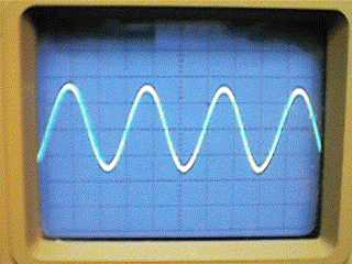 |
| Range 6 | Range 5 | 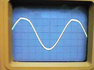 |
| Range 7 | Range 8 | 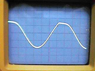 |
| Range 9 | Range 10 | 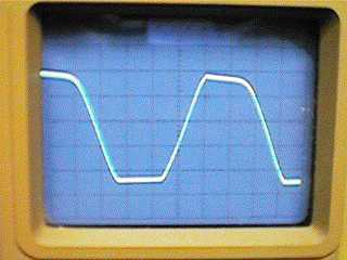 |
| Range | Voltage (Peak-Peak) |
|---|---|
| 1 | 0.3 |
| 2 | 0.65 |
| 3 | 1.3 |
| 4 | 3 |
| 5 | 3 |
| 6 | 5 |
| 7 | 3.5 (top clipped) |
| 8 | 4 (top clipped) |
| 9 | 6 (flat top and bottom) |
| 10 | 6 (flat top and bottom) |