This page describes the boot sequence of an Amstrad PCW, including the contents of its minimal "boot ROM". This information was derived from oscilloscope traces of the data and address lines at power-on.
In summary, the observed boot sequence is:
Execution begins at address 0000h.
The PCW comes up in a special "bootstrap mode". This mode of operation appears to be such that:
The "special" fetches are stretched using the /WAIT signal, and are very slow, a typical M1 cycle taking about 18.3us. The whole sequence takes about 15ms to execute.
Note that different data values are fetched from the same memory address at different times. Also, the location from which the boot ROM is copied depends on the startup value of the HL register, which "Undocumented Z80" says is indeterminate (but tends towards FFFFh, which is what was always observed).
This suggests that whatever is providing the data (gate array and/or printer controller) is ignoring the address lines for memory fetches, and returning a pre-ordered sequence of data for both program and data fetches.
The first instructions executed are additional to the 256 bytes of boot ROM which are usually quoted, and are mostly repetitive (particularly the LDIs). It may be that they are not in ROM per se, but are invented by logic in the gate array and/or printer controller on the fly. Update: John Elliott has obtained a dump of a 9512 printer controller ROM by some means; his partial disassembly indicates that this is indeed the case.
Unlike the boot ROM "proper", there's no reason these first instructions would need to differ between different PCW models and revisions, although there's also no reason they couldn't differ anyway.
These unusual execution properties are presumably the reason for the ROM contents being copied to RAM for execution; it's not possible to execute a real program from the ROM, and in any case, it would probably be too slow to service the FDC.
Disassembly of these first instructions:
0000    AF      XOR     A               ; A = 0
0001    D3      OUT     (0F0h),A        ; Select standard block 0
0002    F0                              ; for both reads and writes
                                        ; 0000h..3FFFh
0003    11      LD      DE,0002h
0004    02
0005    00
0006    ED      LDI
0007    A0
0008    ED      LDI
0009    A0
                ; ...
                ; Snip boring repetitive bit.
                ; There are 256 LDI instructions in total.
                ; These copy 256 bytes from an indeterminate
                ; address range (observed as FFFFh..00FEh with
                ; wrapping) to 0002h..0101h.
                ; Note that the observed source address range overlaps
                ; with these instructions, but different data is
                ; fetched.
                ; ...
0204    ED      LDI
0205    A0
0206    C3      JP      0000h
0207    00
0208    00
                ; Note, different contents again for address 0.
0000    D3      OUT     (0F8h),A        ; A is still 0.
0001    F8
                ; This is the "end bootstrap mode" sequence.
                ; Execution continues in the copied boot ROM, see
                ; below.
These instructions execute from RAM at what is plausibly full speed.
There must clearly be different variants of this code in different PCW models; according to John Elliott, the checksum calculation for the boot sector will be different, and different FDC parameters will presumably be required.
The disassembly is possibly ropey - it was done by hand, and I'm not that familiar with the 765 FDC, so the labels and comments are particularly suspect - but the object code should be accurate. Corrections are welcome.
0002 01 LD BC,83F3h
0003 F3
0004 83
; Set up memory map.
memmaplp:
0005 ED OUT (C),B
0006 41
0007 0D DEC C
0008 78 LD A,B
0009 05 DEC B
000A 87 ADD A,A
000B 20 JR NZ,memmaplp
000C F8
; At this point, we have:
; F3 = 83 standard block 3 0xC000..0xFFFF
; F2 = 82 standard block 2 0x8000..0xBFFF
; F1 = 81 standard block 1 0x4000..0x7FFF
; F0 = 80 standard block 0 0x0000..0x3FFF
000D 31 LD SP,FFF0h ; stack below memory-mapped keyboard
000E F0
000F FF
0010 3E LD A,9
0011 09
0012 D3 OUT (0F8h),A ; start drive motor(s)
0013 F8
0014 11 LD DE,0732h ; E = wait_for_disc loop variable
; D affects no. beeps on error
0015 32
0016 07
; Sit around for about 100 seconds, prodding the
; FDC every so often to see if there's a disc.
wait_for_disc:
0017 06 LD B,0C8h
0018 C8
0019 DC CALL C,delay
001A B1
001B 00
001C CD CALL try_read
001D 84
001E 00
001F 1D DEC E
0020 F2 JP P,wait_for_disc
0021 17
0022 00
; Timeout or error -- the bleeps of DOOM
error:
0023 3E LD A,80h
0024 80
0025 D3 OUT (0F7h),A ; bright video
0026 F7
motor_off:
0027 0E LD C,9 ; inc to func 10 => motors off
0028 09
; This loop will cycle through
; { 10=motors off, 11=beeper on, 12=beeper off }
; with equal delay between each.
; Motors-off does nothing after the first time;
; the effect is to give a 1/3 beeper duty cycle.
; If D=7 on entry we get three beeps.
alarums:
0029 0C INC C
002A 79 LD A,C
002B D3 OUT (0F8h),A
002C F8
002D 06 LD B,21h
002E 21
002F CD CALL delay
0030 B1
0031 00
0032 CB BIT 2,C ; has C reached func 12 (beeper off)?
0033 51
0034 20 JR NZ,motor_off ; yes, reset C
0035 F1
0036 15 DEC D
0037 20 JR NZ,alarums
0038 F0
; Wait for user to press space bar.
0039 21 LD HL,0FFF5h ; memory-mapped keyboard
003A F5
003B FF
003C 77 LD (HL),A ; A=10; ?
keyblp:
003D CB BIT 7,(HL) ; space bar
003E 7E
003F 28 JR Z,keyblp
0040 FC
0041 3C INC A ; A=11; bleeper?
0042 D3 OUT (0F8h),A
0043 F8
; fall through:
; Do something with interrupts,
; then read a sector from the disc to 0F000h.
; If successful, does not return but executes
; boot sector from disc.
; Clobbers: A
; Reduces E by 2 (we're less patient with unsuccessful
; reads than total absence of disc).
fdc_read:
0044 1D DEC E
0045 1D DEC E
0046 3E LD A,6 ; clear FDC terminal count
0047 06
0048 D3 OUT (0F8h),A
0049 F8
004A CD CALL wait_clear
004B E4
004C 00
004D 09 DB 9 ; length of following:
004E 66 DB 66h ; READ DATA,
; MT=0 (multi-track=0),
; MF=1 (MFM),
; SK=1 (skip del. addr mark)
004F 00 DB 0 ; Head 0, unit 0
0050 00 DB 0 ; Cylinder
0051 00 DB 0 ; Head
0052 01 DB 1 ; Record
0053 02 DB 2 ; No. bytes in sector = 512
; (+MT,MF = 15 sectors)
0054 01 DB 1 ; EOT (last sector in track)
0055 2A DB 2Ah ; GPL = gap length
0056 FF DB 0FFh ; DTL = data len (unused)
; control returns here:
0057 21 LD HL,0F000h ; stuff from FDC goes here
0058 00
0059 F0
fdcrdy3:
005A DB IN A,(0) ; FDC status register
005B 00
005C 87 ADD A,A
005D 30 JR NC,fdcrdy3 ; wait for data register ready (b7)
005E FB
005F 87 ADD A,A
0060 F2 JP P,fdcdone ; b5: 1=busy, 0=done (in which case jump)
0061 6B
0062 00
0063 ED INI ; C => (HL)++, B--
0064 A2
0065 20 JR NZ,fdcrdy3 ; while any bit in status[6:0]
0066 F3
0067 7C LD A,H
0068 1F RRA ; b0 of H set? (HL=F1xx, F3xx, ...)
0069 38 JR C,fdcrdy3 ; yes, loop back
006A EF
fdcdone:
006B 3E LD A,5 ; set FDC terminal count
006C 05
006D D3 OUT (0F8h),A ; terminate FDC operation?
006E F8
006F CD CALL fdcin ; get status of read
0070 C7
0071 00
0072 E6 AND 0CBh ; IC|NR|US = bad news
0073 CB
0074 C0 RET NZ ; return if bad news
0075 47 LD B,A ; B=0
0076 21 LD HL,0F010h ; start of boot sector code
0077 10
0078 F0
; Boot sector checksum
; Sum 512 bytes F000..F1FF, starting and ending
; at F010.
cklp: ; boot sector checksum
0079 24 INC H
007A 86 ADD A,(HL)
007B 25 DEC H
007C 86 ADD A,(HL)
007D 2C INC L
007E 10 DJNZ cklp ; 256 times
007F F9
0080 3C INC A ; sum should be 0FFh
0081 20 JR NZ,error ; oh dear. Complain
0082 A0
; Transfer control to boot sector!
0083 E9 JP (HL)
; Try to read and execute bootsector.
; If successful, does not return.
; Clobbers: A, BC, HL
; May decrement E
try_read:
0084 0E LD C,80h ; bright screen
0085 80
0086 CD CALL vid_fdc
0087 DB
0088 00
0089 05 DB 5 ; length of:
008A 03 DB 3 ; SPECIFY
008B 0F DB 0Fh ; SRT (stepping rate time) = 1ms,
; HUT (head unload time) = 240ms
008C FF DB 0FFh ; HLT (head load time) = 254ms,
; ND (non-DMA) = yes
008D 07 DB 7 ; RECALIBRATE (=> track 0)
008E 00 DB 0 ; unit 0
; control returns here
008F CD CALL wait_int
0090 A5
0091 00
0092 06 LD B,0C8h
0093 C8
0094 38 JR C,delay ; delay and return to caller
; if the results were bad
0095 1B
0096 CD CALL fdc_read ; Try to read and execute bootsector
0097 44
0098 00
0099 CD CALL fdc_read ; Once more for luck
009A 44
009B 00
; If we ended up here, we weren't successful
; reading the boot sector.
009C 0E LD C,0 ; dark screen
009D 00
009E CD CALL vid_fdc
009F DB
00A0 00
00A1 03 DB 3 ; length for:
00A2 0F DB 0Fh ; SEEK
00A3 00 DB 0 ; head 0, unit 0
00A4 14 DB 20 ; NCN (cyl = track)
; control returns here
; Wait for interrupt, check return status.
; Carry set = bad, clear = ok.
; Clobbers: A, BC, HL
wait_int: ; wait for interrupt?
00A5 CD CALL fdc_int
00A6 BD
00A7 00
00A8 30 JR NC,wait_int ; NC => no interrupt
; A has ST0 from FDC response
00A9 FB
00AA 17 RLA ; bit 7 of ST0
00AB 38 JR C,wait_int ; IC=1x: invalid command or
; ready changed state during
00AC F8
00AD 17 RLA ; bit 6 of ST0
00AE D8 RET C ; IC=01: abnormal termination
; else IC=00, normal termination
00AF 06 LD B,14h ; delay then return to caller
00B0 14
; fall through to:
; Delay loop. B is length of delay.
; Clobbers: A. (Preserves carry.)
delay:
00B1 3E LD A,0B3h
00B2 B3
delaylp: ; inner loop controlled by A
00B3 E3 EX (SP),HL ; beefy NOPs?
00B4 E3 EX (SP),HL
00B5 E3 EX (SP),HL
00B6 E3 EX (SP),HL
00B7 3D DEC A
00B8 20 JR NZ,delaylp
00B9 F9
00BA 10 DJNZ delay
00BB F5
00BC C9 RET
; Sense/handle FDC interrupt
; None: flags = NC, Z (clobbers: A)
; Int: carry is set (clobbers: A, BC, HL)
fdc_int:
00BD DB IN A,(0F8h)
00BE F8
00BF E6 AND 20h ; Disc controller interrupt status
00C0 20
00C1 C8 RET Z ; No interrupt, presumably
; Work out what the interrupt was.
00C2 CD CALL fdcout
00C3 E9
00C4 00
00C5 01 DB 1, 8 ; SENSE INTERRUPT STATUS
00C6 08
; fall through (with C=1) to:
; Pull response from FDC
; First byte returned in A
; C must be 1 (fdcout leaves it that way)
; Clobbers: A, B, HL
fdcin:
00C7 21 LD HL,fdc_response ; where FDC response data goes
00C8 02
00C9 01
fdcrdy2:
00CA DB IN A,(0) ; FDC status register
00CB 00
00CC 87 ADD A,A
00CD 30 JR NC,fdcrdy2 ; wait for data register ready
00CE FB
00CF 3A LD A,(fdc_response) ; first byte of FDC response
00D0 02
00D1 01
00D2 F0 RET P ; status:d6=0 => FDC wants data (ie done)
; else d6=1, incoming data from FDC
00D3 ED INI ; from C => (HL)++, B--
00D4 A2
00D5 E3 EX (SP),HL ; wait for at least 12us
00D6 E3 EX (SP),HL
00D7 E3 EX (SP),HL
00D8 E3 EX (SP),HL
00D9 18 JR fdcrdy2 ; more response data
00DA EF
; Change screen colour to C, wait for interrupt clear,
; then send FDC command.
; Clobbers: A, BC, HL?
vid_fdc:
00DB DB IN A,(0F8h)
00DC F8
00DD E6 AND 40h ; Frame Flyback Time
00DE 40
00DF 28 JR Z,vid_fdc ; wait for frame flyback
00E0 FA
00E1 79 LD A,C
00E2 D3 OUT (0F7h),A ; video control
00E3 F7
; fall through:
; Wait for an interrupt status to clear,
; then send FDC command.
; Clobbers: A, BC, HL?
wait_clear:
00E4 CD CALL fdc_int
00E5 BD
00E6 00
00E7 38 JR C,wait_clear ; NC => no interrupt
00E8 FB
; fall through:
; Output a variable number of bytes to the FDC.
; Bytes are stored after CALL -- this function will
; modify return address.
; Side effect: sets C register to 1 (used elsewhere)
; Clobbers: A, BC
fdcout:
00E9 E3 EX (SP),HL ; return address in HL
00EA 46 LD B,(HL) ; count of output data
00EB 23 INC HL ; move ret addr over count
00EC E3 EX (SP),HL
00ED 0E LD C,1 ; FDC data register port
00EE 01
fdclp:
00EF E3 EX (SP),HL ; return address in HL
fdcrdy:
00F0 DB IN A,(0) ; FDC status register
00F1 00
00F2 87 ADD A,A
00F3 30 JR NC,fdcrdy ; wait for data register ready (b7)
00F4 FB
00F5 FA JP M,fdcrd ; b6 set => incoming data
00F6 FB ; else OK to write data out:
00F7 00
00F8 7E LD A,(HL) ; outgoing command byte
00F9 ED OUT (C),A ; to data register
00FA 79
fdcrd:
00FB 23 INC HL ; next command byte
00FC E3 EX (SP),HL ; wait for at least 12us
00FD E3 EX (SP),HL
00FE E3 EX (SP),HL ; return address now back on stack
00FF 10 DJNZ fdclp
0100 EE
0101 C9 RET ; having skipped bytes
fdc_response:
0102 ; response bytes go here
Salient points about the environment the boot sector is executed in, derived from the above disassembly. (John Elliott has some more information about the format of PCW boot sectors.)
(I have a half-finished disassembly of an 8000-series boot sector from years ago lying around somewhere.)
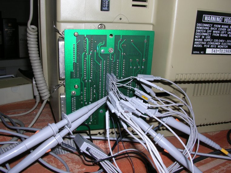
This scope has 16 data probes and 4 analogue probes. In order to verify the entire 16-bit address bus, 8-bit data bus, and various control lines, data from several runs was combined, with care taken to ensure that this gave a consistent view of events.
The PCW's edge connector is awkward to probe. However, an expansion pack (I used a CPS8256) with the case removed provides a convenient place to mount digital probes (see photo).
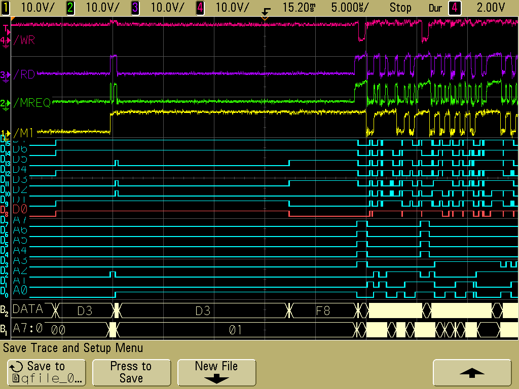
An example scope trace from this setup, taken at the point where we start running from RAM.
The fact that the ROM contents were copied out sequentially made this much easier than I thought it was going to be; I thought I'd have to find inventive ways of exercising every code path in the boot ROM in order to see it all, or end up with holes in my disassembly.